-
Email us at:
info@weltreatsystems.com -
Call us on:
020 - 41228334 - Download Brochure

27
May 26How Industrial RO Plant Works — Complete Stage by Stage Guide
- May 27, 2026
- Industrial RO Plant Reverse Osmosis System RO Membrane RO Plant Maintenance Water Treatment
Industrial RO plants are used across manufacturing industries to remove dissolved salts, reduce TDS, and produce high-quality process water. However, many industries invest in RO systems without fully understanding how each stage of the process works.
An industrial RO plant is much more than membranes and pumps. Every treatment stage—from raw water storage and filtration to antiscalant dosing and membrane separation—plays a critical role in protecting equipment and ensuring long-term performance.
This guide explains how an industrial RO plant works step by step, including all major components, recovery rates, membrane operation, concentrate management, and common performance issues faced by industries in India.
What Reverse Osmosis Actually Does
Osmosis is a natural process — water moves from a low-concentration solution through a semi-permeable membrane toward a high-concentration solution, equalising the concentration on both sides.
Reverse Osmosis does the opposite. By applying pressure greater than the osmotic pressure of the feed water, water molecules are forced through the membrane from the high-concentration (feed) side to the low-concentration (permeate) side. Dissolved salts, ions, organics, bacteria, and most contaminants cannot pass through the membrane — they are retained in the concentrate stream.
The result is two streams:
Permeate — purified water that has passed through the membrane. Low TDS, low conductivity, suitable for process use, utilities, or reuse.
Concentrate (Reject) — the remaining water with concentrated dissolved solids. This stream must be managed — discharged to CETP if permitted, or processed further in ZLD systems.
For industries exploring how RO integrates into a full Zero Liquid Discharge system, read our ZLD vs ETP vs ETP+RO comparison guide.
The Complete Industrial RO Process — Every Stage
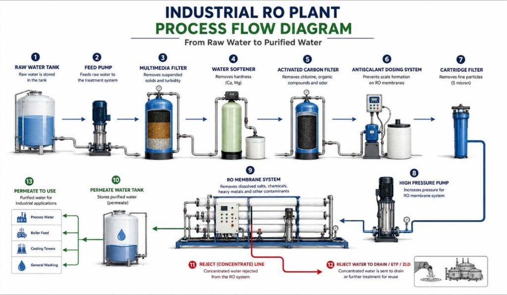
An industrial RO system is not just a pressure pump and membranes. It is a multi-stage engineered process. Every stage upstream of the membranes exists to protect them. Every stage downstream conditions the permeate for its intended use.
| Stage | Function |
|---|---|
| Raw Water Tank | Water Storage |
| Feed Pump | Water Transfer |
| Multimedia Filter | Turbidity Removal |
| Softener | Hardness Reduction |
| Carbon Filter | Chlorine Removal |
| Antiscalant Dosing | Scale Prevention |
| Cartridge Filter | Fine Filtration |
| High Pressure Pump | Pressure Generation |
| RO Membrane | Purification |
| Permeate Tank | Water Storage |
Stage 1 — Raw Water Storage and Feeding
Feed water — whether from borewell, municipal supply, river, or treated effluent — enters a raw water storage tank. This provides a buffer for continuous RO operation independent of supply fluctuations.
A feed pump transfers water from the storage tank to the pre-treatment train at the required flow rate. Consistent, steady flow is important for pre-treatment performance.
Why it matters: Pressure fluctuations and intermittent feeding cause uneven loading on pre-treatment systems and destabilise chemical dosing — leading to poor pre-treatment and accelerated membrane fouling.
Stage 2 — Pre-Screening and Coarse Filtration
Raw water first passes through a strainer or coarse filter — typically 100 to 200 micron mesh — to remove large suspended particles, sand, insects, and debris that could damage downstream equipment.
For feed water with high suspended solids — borewell water, river intake, or treated effluent from an ETP — a multimedia filter (sand and gravel layers) may be included here to remove turbidity before chemical dosing begins.
Why it matters: Large particles damage valve seats, clog chemical dosing lines, and rapidly foul cartridge filters and membranes if not removed upstream.
Stage 3 — Coagulation and Flocculation (Where Required)
For feed water with high colloidal content — common in surface water, treated effluent, or certain borewell sources — coagulation chemicals (ferric chloride, polyaluminium chloride) are dosed to destabilise colloidal particles and cause them to clump. A flocculation tank allows these clumps to grow before removal in a downstream filter.
This stage is included in RO systems for feed water where SDI (Silt Density Index) cannot be reduced to below 5 through filtration alone.
Why it matters: Colloids below 1 micron pass through multimedia filters but foul RO membranes progressively. Removing them upstream through coagulation dramatically extends membrane life.
Stage 4 — Water Softening (Where Required)
If your feed water has high hardness — elevated calcium and magnesium — a water softener is installed upstream of the RO. The softener exchanges calcium and magnesium ions for sodium ions using resin beds, reducing scaling potential on RO membranes.
Alternatively, for lower hardness levels, antiscalant dosing alone (Stage 6) may be sufficient without full softening.
Why it matters: Calcium carbonate and calcium sulphate scale on RO membranes is one of the two most common causes of premature membrane failure in Indian industrial plants. The right pre-treatment choice depends on your specific feed water chemistry.
Stage 5 — Activated Carbon Filter (Where Required)
If your feed water contains free chlorine — municipal supply is typically chlorinated — an activated carbon filter or sodium bisulphite dosing is essential upstream of the RO membranes.
Polyamide RO membranes — the most common type used in industrial applications — are rapidly and irreversibly damaged by free chlorine. Even a short exposure to chlorinated water can permanently compromise membrane performance.
Why it matters: Chlorine damage to RO membranes is instant and irreversible. There is no cleaning procedure that recovers a chlorine-damaged membrane. This stage protects a significant capital investment.
Stage 6 — Antiscalant Dosing
A dosing pump injects liquid antiscalant chemical into the feed water at a precisely controlled rate immediately before the cartridge filter. Antiscalant prevents scale-forming salts — calcium carbonate, calcium sulphate, barium sulphate, silica — from precipitating on membrane surfaces during concentration inside the pressure vessel.
The correct antiscalant type and dose are calculated from your feed water analysis. Using the wrong antiscalant or incorrect dosing rate is one of the most common causes of scaling in Indian industrial RO plants.
Why it matters: Antiscalant is the primary chemical protection for your membranes. Even a few hours of operation without antiscalant dosing can initiate scaling that requires acid cleaning to reverse.
For a complete guide to RO maintenance including antiscalant management, read our RO plant maintenance 12-month schedule.
Stage 7 — Cartridge Filter (Micron Filter)
The final pre-treatment stage before the high-pressure pump is a cartridge filter — typically 5 micron nominal, sometimes 1 micron depending on the system design. This filter removes any residual fine particles that have passed through upstream stages.
Cartridge filters are consumables. They must be replaced regularly — typically every 1 to 3 months depending on feed water turbidity — regardless of whether the differential pressure indicator shows blockage.
Why it matters: Cartridge filters are the last line of defence for the RO membranes. A fouled cartridge filter forces suspended solids directly onto the membrane surface. This is the most common cause of preventable membrane fouling in Indian industrial RO plants.
Stage 8 — High-Pressure Pump
The high-pressure pump is the heart of the RO system. It pressurises pre-treated feed water to the operating pressure required to overcome the osmotic pressure of the feed water and force permeate through the membranes.
Operating pressures for common applications:
Brackish water RO (TDS 1,000 to 10,000 mg/L): 10 to 20 bar High TDS RO (TDS 10,000 to 30,000 mg/L): 20 to 40 bar Seawater RO: 55 to 70 bar
Most industrial RO plants in India operate in the brackish water pressure range. The pump is typically a multistage centrifugal or positive displacement type, selected for efficiency at the required pressure and flow.
Why it matters: Operating pressure that is too low reduces permeate flux and recovery. Operating pressure that is too high accelerates membrane compaction and reduces membrane life. Correct pump selection and pressure control are fundamental to RO performance.
Stage 9 — RO Membrane Vessels and Elements
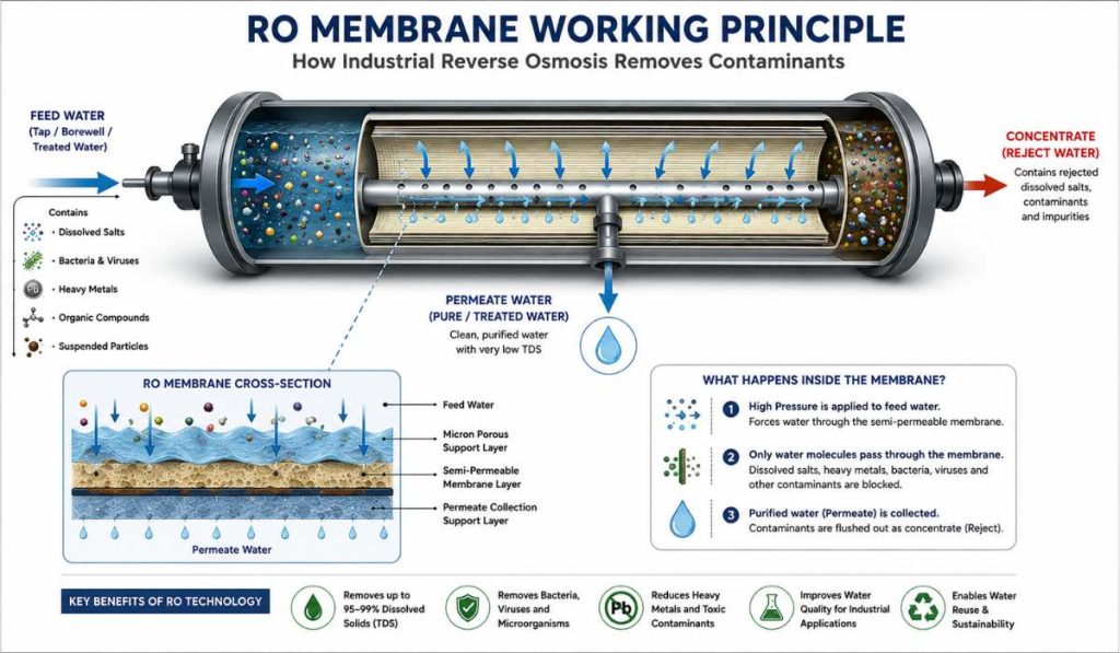
This is where the actual separation happens. Feed water under pressure enters pressure vessels — typically fibre-reinforced plastic (FRP) cylinders — each containing 4 to 7 spiral-wound membrane elements in series.
Each membrane element consists of flat membrane sheets wound around a central permeate collection tube. Feed water flows along the membrane surface under pressure. Water permeates through the membrane into the central tube. Dissolved salts, organics, bacteria, and particulates are rejected and flow out as concentrate.
Membrane arrangement — series and parallel:
Elements in series (within one vessel): Concentration of the feed increases from element to element as permeate is removed. The last element in a vessel sees the highest concentration and has the lowest flux.
Vessels in parallel: Multiple vessels receive feed simultaneously to achieve the required total flow rate.
Multi-stage systems (array): For high recovery requirements, concentrate from the first stage of vessels becomes feed for a second stage. This is common for systems targeting 75 percent or higher recovery.
Why it matters: Membrane element configuration determines your system’s recovery rate, pressure profile, and overall efficiency. Incorrect configuration leads to either low recovery (wasting water) or high concentration polarisation (fouling last elements).
Stage 10 — Permeate Collection and Quality Check
Permeate from all membrane elements is collected in a permeate header. An online conductivity meter continuously measures permeate TDS. A sudden increase in permeate conductivity indicates membrane damage, O-ring failure, or interconnector leakage — all of which require immediate investigation.
Why it matters: Continuous conductivity monitoring is the earliest warning system for membrane integrity failure. Without it, a membrane failure can go undetected for weeks, contaminating your process water supply.
Stage 11 — Concentrate Management
Concentrate exits the last stage of membrane vessels and must be managed according to your consent conditions. Options:
Discharge to CETP (if permitted and CETP accepts the TDS and volume) Partial recirculation to increase recovery (common in water-stressed applications) Feed to ZLD system — MEE or evaporation pond for further concentration and water recovery
Why it matters: The concentrate management decision must be made before system design, not after. A system designed for CETP discharge that subsequently loses CETP access has no legal outlet for its concentrate — a regulatory problem that is expensive to resolve after installation.
Stage 12 — Post-Treatment of Permeate
RO permeate is slightly acidic (pH typically 5.5 to 6.5 after CO2 passage through membranes) and very low in minerals. Depending on end use, post-treatment may include:
pH correction: Caustic soda or lime dosing to raise pH to 7.0 to 7.5 for process or utility use.
Mixed Bed Deionisation (MB-DI): For pharmaceutical or electronic grade water requirements where even trace ions must be removed after RO.
UV disinfection: For water used in food contact or human consumption applications.
Re-mineralisation: For drinking water applications where mineral content is desired.
Why it matters: Using RO permeate without pH correction in boiler systems causes carbonic acid corrosion. Using it without UV in food applications creates microbiological risk. Post-treatment matches permeate quality to end-use requirements.
Stage 13 — Permeate Storage and Distribution
Treated permeate is stored in a product water tank — typically sized for 2 to 4 hours of downstream demand — before distribution to end-use points. The product tank provides a buffer to decouple RO production rate from demand fluctuation.
RO System Recovery Rate — What It Means and Why It Matters
Recovery rate is the percentage of feed water that becomes permeate. A system operating at 75 percent recovery produces 75 litres of permeate for every 100 litres of feed water fed to the system. The remaining 25 litres exits as concentrate.
Higher recovery means less feed water consumed and less concentrate to manage. But higher recovery also means higher concentration factor in the concentrate stream — increasing scaling risk on last-stage membranes.
Typical industrial RO recovery rates:
Standard single-pass RO: 50 to 70 percent Multi-stage RO with recirculation: 70 to 85 percent High-recovery RO with advanced antiscalant and softening: up to 90 percent
Recovery rate is a design parameter — it must be optimised against your feed water chemistry, concentrate disposal constraints, and water cost. It is not simply a setting that can be adjusted on any system.
Key Performance Parameters to Monitor
- Feed Water TDS
- Permeate Conductivity
- Feed Pressure
- Recovery Rate
- Differential Pressure
- Permeate Flow Rate
- Concentrate Flow Rate
- SDI Value
Common Industrial Applications of RO Plants
- Pharmaceutical Industry
- Food and Beverage Manufacturing
- Textile Industry
- Chemical Processing Plants
- Automobile Manufacturing
- Boiler Feed Water Systems
- Cooling Towers
- Industrial Wastewater Reuse
- Zero Liquid Discharge Projects
What Can and Cannot Pass Through an RO Membrane
| Parameter | Sand Filter | UF | RO |
|---|---|---|---|
| Removes TDS | No | No | Yes |
| Removes Bacteria | Limited | Yes | |
| Removes Viruses | No | Partial | Yes |
| Operating Pressure | Low | Medium | High |
| Industrial Reuse | Limited | Moderate | Excellent |
Rejected by RO membrane (does not pass through):
- Dissolved salts and ions (calcium, magnesium, sodium, chloride, sulphate, nitrate)
- Heavy metals (lead, arsenic, chromium, iron, manganese)
- Bacteria and viruses (greater than 99.9 percent rejection)
- Most organic compounds with molecular weight above 200 daltons
- Colloids and fine particles
Passes through RO membrane:
- Water molecules
- Dissolved gases (CO2, H2S, O2) — these pass freely through membranes
- Very small organic molecules below 100 daltons (trace pesticides, certain pharmaceuticals at low concentration)
Why this matters for industrial applications: CO2 passage through membranes is the reason RO permeate is typically acidic. H2S passage is why permeate can carry a sulphur odour in some borewell applications. Awareness of what passes and what is rejected is essential for specifying post-treatment correctly.
Common Reasons Industrial RO Plants Underperform in India
Inadequate pre-treatment. The majority of premature membrane fouling in Indian industrial RO plants is caused by inadequate pre-treatment — insufficient SDI reduction, inconsistent antiscalant dosing, or no activated carbon for chlorinated feed water. Pre-treatment investment directly determines membrane life.
Incorrect antiscalant selection. Generic antiscalant dosed without feed water analysis frequently fails to prevent the specific scaling species in your water. A proper antiscalant recommendation requires your full water analysis — not just TDS.
Running fouled cartridge filters. This is the single most common maintenance failure in Indian industrial RO operations. Cartridge filters should be replaced on schedule — not only when differential pressure is high.
No performance monitoring. RO systems without regular normalised performance tracking deteriorate gradually without triggering alarm. By the time performance decline is obvious, significant irreversible membrane fouling has occurred.
Incorrect concentrate management. Operating at recovery rates higher than the system design without appropriate antiscalant adjustment leads to rapid scaling of last-stage membranes.
How Weltreat Designs Industrial RO Systems
Every Weltreat RO system begins with a feed water analysis — not an assumption. We calculate the correct pre-treatment train, antiscalant type and dose, recovery rate, and membrane configuration from your actual water quality data.
Our RO systems include proper antiscalant dosing systems, automated CIP connections, online conductivity monitoring, and concentrate management provisions — not value-engineered out of the design.
For RO plant supply and installation in Pune and Maharashtra, visit our RO plant service page.
For a complete guide to industrial RO plants including types, applications, and cost, read our industrial RO plant complete guide.
Frequently Asked Questions
What is the difference between RO and UF?
RO removes dissolved salts and ions by forcing water through a membrane under high pressure, significantly reducing TDS. UF removes suspended solids, bacteria, and viruses through a lower-pressure membrane process but does not remove dissolved salts. UF is often used as a pretreatment stage before RO.
Why does RO permeate taste flat or slightly acidic?
RO removes minerals such as calcium, magnesium, and bicarbonates from water. The absence of these minerals can make water taste flat. In addition, dissolved carbon dioxide (CO₂) can pass through RO membranes, resulting in a slightly acidic pH. Remineralisation and pH correction are commonly used in drinking water applications.
What is SDI and why is it important for RO?
Silt Density Index (SDI) measures the fouling potential of feed water. Most RO membrane manufacturers recommend feed water SDI below 5, while SDI below 3 is preferred for optimal membrane performance and life. High SDI can lead to rapid membrane fouling and increased maintenance requirements.
How much water does an industrial RO system waste?
Water loss depends on the system recovery rate. A system operating at 75% recovery produces 75 litres of permeate from every 100 litres of feed water, while the remaining 25 litres become concentrate. Advanced systems can achieve recovery rates of 85% or higher under suitable operating conditions.
Can RO remove all contaminants from industrial effluent?
No. RO removes most dissolved salts, heavy metals, bacteria, viruses, and larger organic compounds. However, certain dissolved gases and very small organic molecules may pass through the membrane. RO is typically used as part of a complete treatment process rather than as a standalone solution.
How long do industrial RO membranes last?
Industrial RO membranes typically last between 3 and 7 years, depending on feed water quality, pretreatment effectiveness, operating conditions, and maintenance practices. Proper cleaning and monitoring significantly extend membrane life.
What is membrane fouling in an RO plant?
Membrane fouling occurs when suspended solids, organic matter, microorganisms, or other contaminants accumulate on the membrane surface. Fouling reduces permeate production, increases operating pressure, and lowers overall system efficiency.
What is CIP cleaning in an industrial RO system?
CIP (Clean-in-Place) is a maintenance procedure used to remove scale, fouling, and biological deposits from RO membranes without dismantling the system. Proper CIP cleaning helps restore performance and prolong membrane life.
Can RO water be used directly in boilers?
RO water is commonly used for boiler feed applications because of its low dissolved solids content. However, high-pressure boilers often require additional treatment such as mixed bed deionisation (MB-DI), deaeration, or pH adjustment to meet water quality specifications.
How often should cartridge filters be replaced in an RO plant?
Cartridge filters are generally replaced every 1 to 3 months, depending on feed water quality and operating conditions. Regular replacement helps protect RO membranes from suspended solids and prevents premature fouling.
What is the ideal recovery rate for an industrial RO plant?
The ideal recovery rate depends on feed water chemistry, scaling potential, and concentrate disposal requirements. Most industrial RO systems operate between 50% and 80% recovery. Higher recovery improves water efficiency but also increases scaling risk, making proper design and chemical dosing essential.
Also Read
- Industrial RO Plant Complete Guide India
- RO Plant Maintenance — 12-Month Schedule
- ZLD vs ETP vs ETP+RO — Which System Does Your Industry Need
- ETP Complete Guide India 2025
- ZLD System Cost India — Full Budget Breakdown
Key Takeaways
- RO membranes perform the actual separation process.
- Pretreatment directly affects membrane life.
- Antiscalant dosing helps prevent scaling.
- Recovery rate impacts water efficiency and scaling risk.
- Continuous conductivity monitoring is essential.
- Proper concentrate management should be planned during design.
Need Help Selecting the Right Industrial RO Plant?
The correct RO design depends on feed water chemistry, required recovery rate, water consumption, and concentrate disposal options.
A detailed feed water analysis helps determine:
- Membrane selection
- Recovery rate
- Pretreatment requirements
- Antiscalant dosage
- Concentrate management strategy
Contact Weltreat Systems for a detailed water analysis and RO system recommendation.